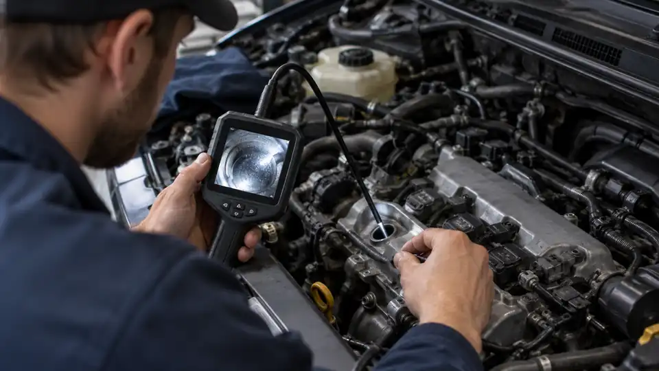
Inspecting an engine cylinder with a borescope usually means entering through a removed spark plug hole, or through an approved glow plug access point on some diesel engines. The aim is to obtain controlled views of the piston crown, cylinder wall, and, if the angle allows, the valves. A useful inspection depends less on pushing the probe as far as possible than on keeping the camera lens clean, the probe oriented, and the working distance close enough to show surface detail.
Prepare the Engine and Inspection Camera
Work with the engine off and follow the vehicle manufacturer’s service procedure to prevent accidental starting. Let hot components cool to conditions suitable for the borescope and the camera’s stated operating limits. Remove the ignition key or otherwise secure the vehicle as appropriate, then clean the area around the plug or access opening so loose grit cannot fall into the cylinder.
Before inserting the probe, check that its camera head will pass through the opening without catching. A slim probe may reach the combustion chamber more easily, while a larger camera head may provide different lighting or image quality. The smallest probe is not automatically the best choice, since cable control, focus, and the ability to hold a steady view matter just as much once the tip is inside.
- Charge or connect the borescope and confirm that the live image appears.
- Wipe the lens according to the manufacturer’s cleaning instructions.
- Check that the probe is free of grit, metal particles, and residue from an earlier inspection.
- Confirm that the probe and camera head are suitable for the temperature and fluid exposure expected during the inspection.
- Set up the display or recording function before the probe enters the cylinder.
A dirty lens can make a clean piston look smeared, while excessive brightness can wash out reflective aluminum or wet-looking areas. Start with moderate lighting, then adjust the camera angle and distance before turning the LEDs up to maximum.
Reach the Cylinder Through the Access Opening
Insert the probe slowly through the spark plug hole, keeping the camera head aligned with the opening. A flexible cable bends easily but does not necessarily steer the tip. A semi-rigid probe can hold a gentle curve, while an articulating probe uses a control to redirect the camera head. These behaviors affect how quickly you can move from the piston crown to the cylinder wall.
Use the cable with small push-and-rotate movements rather than long, forceful strokes. If the tip meets unexpected resistance, stop and withdraw it slightly. The obstruction could be the edge of the opening, a valve, a piston feature, or another internal component. Applying more force can damage the probe or disturb engine parts, and it rarely produces a better image.
Once the camera enters the combustion chamber, identify its orientation. The top of the display may not correspond to the top of the engine, especially after the cable twists. Make a slow rotation of the probe and watch how the piston and cylinder wall move on screen. This simple check prevents a common mistake: recording several close-ups without knowing which side of the cylinder each view represents.
Start With a Wide View of the Piston Crown
Move the camera until most of the piston crown appears on screen. A wider view gives you a reference for later close-ups and helps show whether a dark area is localized or spread across the surface. Keep the tip steady for a moment, since cable movement can blur fine surface marks and make a deposit appear rougher than it is.
Look for visible features such as uneven coloration, wet-looking residue, unusual deposits, impact marks, or a surface area that appears different from the rest of the piston. Describe what is actually visible. A dark patch may be carbon, oil-related residue, or simply a shadow created by the camera angle. A bright spot may be exposed metal or glare from the LEDs. The image alone usually cannot establish the material’s identity or the cause of the appearance.
Change the camera angle before increasing brightness. Reflective piston surfaces can produce a sharp white glare that hides detail, while a slight tilt may reveal the texture around it. If the image becomes clearer after the probe moves a few millimeters, the original problem was probably working distance or reflection rather than insufficient resolution.
Inspect the Cylinder Wall Around Its Travel
After viewing the piston crown, angle the camera toward the cylinder wall. The wall may appear as a curved strip along the edge of the image, so move slowly and keep the tip close enough for the surface to remain in focus. Rotate the probe in small increments to inspect different sides instead of relying on one narrow view.
Look for visible vertical marks, areas with a different sheen, discoloration, wet-looking streaks, or deposits along the wall. A line that appears crack-like may be a scratch, reflection, residue, or an actual surface defect. The borescope image can justify closer testing, measurement, or disassembly, but it cannot establish the depth or structural significance of a mark by appearance alone.
Inspect several heights if the probe can reach them safely. The piston position changes the amount of wall exposed, so one view may show the upper cylinder area while another reveals a lower section. Compare surfaces using similar lighting and camera distance. A wall that looks bright in one frame and dark in another may simply be reflecting the LEDs at different angles.
Try to View the Valves Without Losing Control
With the piston lowered enough to create a line of sight, carefully redirect the camera toward the upper part of the combustion chamber. Valve visibility depends on the engine design, the access opening, the piston position, and the probe’s steering ability. A flexible cable may bend toward the valve area, but bending the cable alone does not guarantee that the camera points where you need it.
Look for the visible condition of the valve face and nearby chamber surfaces, keeping the wording observational. Uneven deposits, a wet-looking area, or a valve edge that appears different from its neighbor may justify additional diagnosis. The view may be blocked or distorted by glare, and the image cannot confirm valve sealing, compression, timing, or the exact source of a residue.
Do not use the probe as a lever against a valve, piston, or combustion-chamber surface. If the tip repeatedly touches an internal part, retract it and change the entry angle. A few controlled views are more useful than a damaged camera or a forced path.
Use a Repeatable Viewing Sequence
A consistent sequence makes the inspection easier to interpret, especially when comparing cylinders. After reaching the chamber, capture or observe a wide piston view, a closer piston view, several cylinder-wall angles, and a valve-area view if accessible. Keep the probe movement gentle and pause after each adjustment so the image settles.
| View | What to observe | What the image cannot establish alone |
|---|---|---|
| Piston crown | Deposits, unusual coloration, impact-like marks, wet-looking areas, and surface differences | The identity of a residue, the cause of a mark, or the engine’s internal condition as a whole |
| Cylinder wall | Vertical marks, discoloration, uneven sheen, and visible surface irregularities | Exact wear depth, dimensional tolerance, or structural integrity |
| Valve area | Visible deposits, edge appearance, and differences between accessible valve surfaces | Valve sealing, compression, timing, or the source of a visible residue |
| Combustion chamber | General cleanliness, loose-looking material, and areas that differ from nearby surfaces | Definitive diagnosis from appearance alone |
If one cylinder looks different from the others, repeat the view before drawing a conclusion. The camera may be closer, the LEDs may be aimed differently, or the piston may be positioned at another height. Matching the viewing angle and lighting can separate a real difference from an imaging difference.
Improve Blurry or Glare-Filled Images
A blurry image often improves when the probe stops moving and the camera is repositioned within its useful focus range. Wipe the lens if the entire image has a hazy veil. If the center is clear but the edges are soft, move the camera rather than relying heavily on digital zoom, since zoom enlarges captured pixels without adding physical detail.
For glare, lower the lighting, tilt the probe, or view the surface from a slightly different angle. Wet-looking residue and polished metal can reflect the LEDs strongly. A dimmer image with a controlled reflection may show more useful texture than a bright white patch, so brightness should serve the view rather than dominate it.
Compare Cylinders Carefully
Inspection becomes more useful when similar areas are compared. Record which spark plug hole or access point corresponds to each view, then use roughly comparable probe distance, orientation, and lighting for the other cylinders. A close-up from one cylinder should not be compared with a distant, glare-filled image from another.
Look for repeated patterns and isolated differences. Similar deposits across several cylinders may have a different significance from one unusual area, but visual similarity still does not identify the underlying cause. A borescope can help decide whether compression testing, leak-down testing, spark or glow plug checks, fluid checks, or mechanical inspection should follow.
Withdraw the Probe Without Losing the Inspection
Retract the camera slowly while watching the screen for contact with the access opening. Avoid dragging the lens across threads or gritty edges. Once the probe is out, inspect it for residue or damage and follow the manufacturer’s instructions for cleaning. Water resistance, if specified for a particular part of the device, does not automatically mean the entire borescope is safe around fuel, oil, solvents, heat, or other engine fluids.
Save a useful close-up and a wider reference view if the findings may need comparison later. A short note identifying the cylinder and the general camera angle can prevent confusion after several similar-looking images. The most valuable result is a clear observation tied to a specific location, followed by the appropriate mechanical test rather than a diagnosis based on one dramatic frame.
